Design Solutions :-
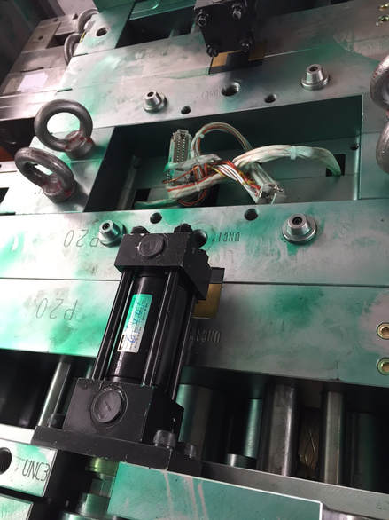
1. Safety Limitation Switches In Tooling Design
2. Overmolding by Double Injection Machine
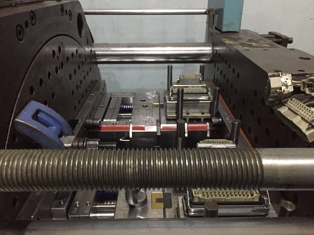
(One Complete Set) (One piece TOP mold clamp plate and One piece BOTTOM mold clamp plate)
|
|
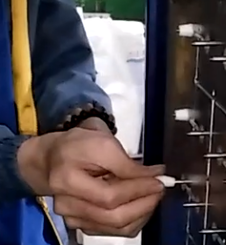
3. Overmolding by Manual Insert molding
Stainless Metal Pins manual insert overmolding
|
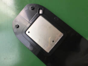
Metal plate manual insert overmolding
|
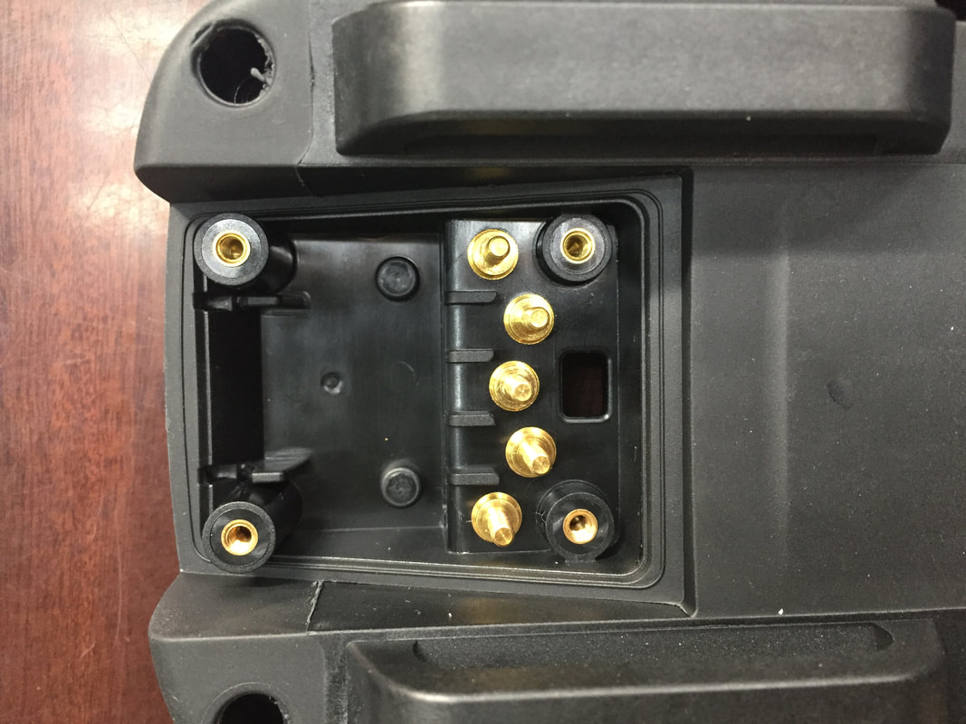
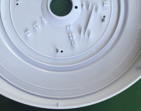
Brass Metal Nuts manual insert overmolding
|
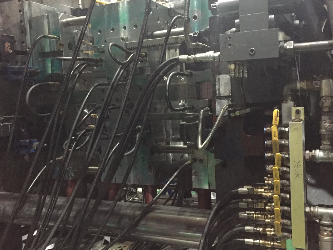
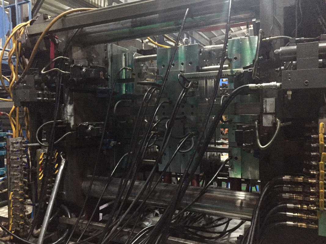
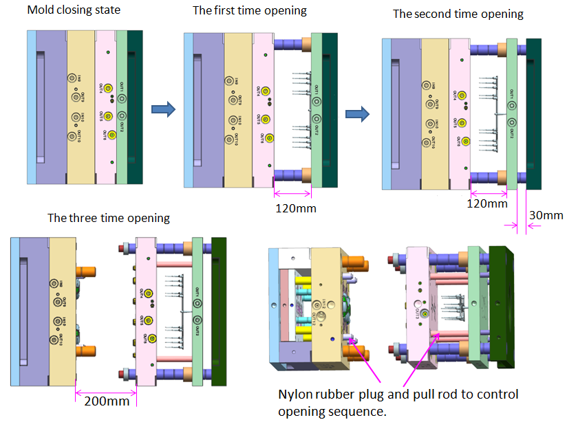
4. Stack mold
Mold in Opening
|
Mold in Closing
|
Top View (hydraulic push-pull system)
|
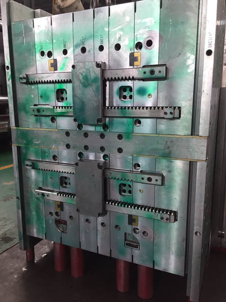
Side View (rack and gear operated motion system)
|
Double Your Machine Output
Compared to conventional single-face molds, stack molds can virtually double the output of an injection molding machine by distributing the plastic melt into two or more separate mold parting surfaces.
What is a Stack Mold?
The defining characteristic of a stack mold are the two (or more) mold parting surfaces or mold split lines. A stack mold does not require much more clamp force than a single face mold because the projected part surface areas of the cavities on both sides of the center block cancel out each others force.
@ Without increasing the machine platen size you can double the amount of cavities producing parts. Most stack molds have an equal number of the same cavities in each parting surface.
@ Some stack molds have different cavities in each mold parting surface and they produce a family of parts per shot, each different in shape and size. This optimizes plastic part quality and the production output by improving cycle time.
@ Some stack molds can also handle multi-material injection, different materials such as hard/soft combination or multi-color molding. Three level stack molds are not as common as two level stack molds.
@ When the stack mold opens for the ejection of parts, both mold parting surfaces open (in most cases simultaneously) by means of a mechanical connection between the mold center block, the fixed halves of the mold and the moving half of the mold. The mechanical connection which moves the center block of the mold can be:
a) rack and gear operated motion system
b) harmonic lever system
c) hydraulic push-pull system or
d) helical gear system
@ Aside from the center block motion system, another key element of a stack mold is the hot runner system. The transfer of plastic melt from the machine barrel into the mold center block has traditionally been achieved by a heated sprue bar which leads the melt from the machine nozzle through the fixed mold half and through the first mold parting surface into the hot runner manifold, which is located in the center block of the stack mold.
@ The relatively simple sprue bar has the disadvantage of getting disengaged from the machine nozzle at each cycle when the mold opens for part ejection. The sprue bar may also become an obstacle during part removal, especially with robot take out/handling equipment because it always remains inside the first mold parting surface.
@ Mold cavities which by design cover the center surface of the molding area do not allow a center sprue bar so the hot runner has to by-pass the melt by leading it with an off-set manifold to the outside of the mold and from the side position through the first mold parting line into the center block for further melt distribution through the nozzles to the cavities.
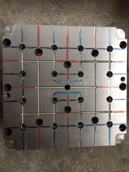
5. Venting
|
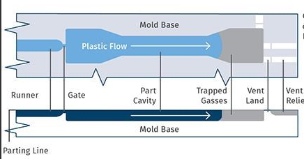
Common part-quality issues such as burns, flash, and warpage cause frequent headaches for molders. Fortunately, careful consideration of one key aspect of mold design—venting—can help eliminate these problems.
Venting is a small part of tool design that has a large effect on part quality, and the number of vents and their locations are therefore critical. But not all plastics designers and processors pay close enough attention to this crucial design aspect. |
6. Insert molding
|
|
7. Three plate mold from Two plate mold
Improve your injection molding
@ The advantage of a three plate mold design is that it permits the gates to be located on top or bottom of the part at any point on the surface. Well placed gates will produce quality parts every cycle.
@ 3 plate mold designs are used in multi cavity cold runner mold tooling when a 2 plate mold design does not permit a suitable gate location. Cold runner are ejected by their own individual stripper plates during mold opening.
8. Plastic Injection Molding techniques:-
Molding Parts defectives and corrective actions:-
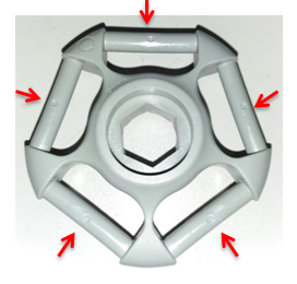
8.1 Warping
Description: Warping is the deformation that occurs when there is uneven shrinkage in the different parts of the molded component. The result is a twisted, uneven, or bent shape where one was not intended.
Causes: Warping is usually caused by non-uniform cooling of the mold material. Different cooling rates in different parts of the mold cause the plastic to cool differently and thus create internal stresses. These stresses, when released, lead to warping.
Remedies:
1. Ensure that the cooling time is sufficiently long and that it is slow enough to avoid the development of residual stresses being locked into the part.
2. Design the mold with uniform wall thickness and so that the plastic flows in a single direction.
3. Select plastic materials that are less likely to shrink and deform.
Semi-crystalline materials are generally more prone to warping.

|
|
