TSY Molding Ltd. co-designs with clients to perfect their product design to re-define ideas and create a manufacturing process , all the way up to products for the quick sales in markets.
Design Rules
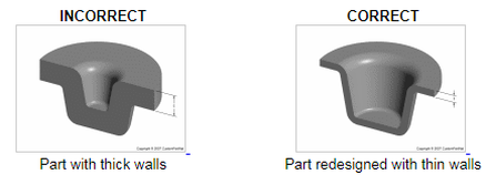
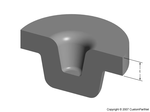
1. Maximum wall thickness
Mold Wall Thickness
Non-uniform wall sections can contribute to warpage and stresses in molded parts.
@ Sections which are too thin have a higher chance of breakage in handling, may restrict the flow of material and may trap air causing a defective part.
@ Too heavy a wall thickness, on the other hand, will slow the curing cycle and add to material cost and increase cycle time.
Generally, thinner walls are more feasible with small parts rather than with large ones. The limiting factor in wall thinness is the tendency for the plastic material in thin walls to cool and solidify before the mold is filled. The shorter the material flow, the thinner the wall can be. Walls also should be as uniform in thickness as possible to avoid warpage from uneven shrinkage. When changes in wall thickness are unavoidable, the transition should be gradual and not abrupt.
Attention:-
Some plastics are more sensitive to wall thickness than others, where acetal and ABS plastics max out at around 3mm thick , acrylic can go to 12 mm, polyurethane to 18 mm, and certain fiber-reinforced plastics to 25 mm or more. Even so, designers should recognize that very thick cross sections can increase the likelihood of cosmetic defects like sink.
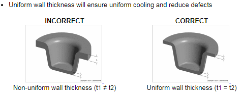
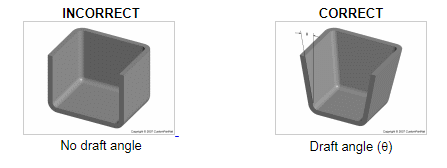
2. Draft
|
|
3. Corners
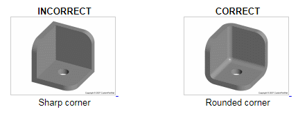
*Round corners to reduce stress concentrations and fracture
- *Inner radius should be at least the thickness of the walls
4. Bosses
|
|
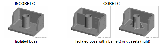
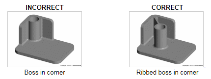
|
5. Parting Line
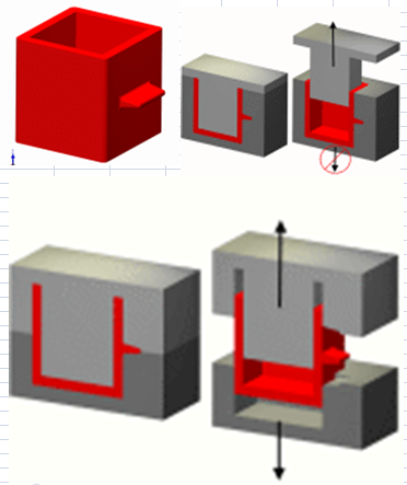
Industrial Part Redesign to cut tooling cost.
Acceptance of mold with new parting line, undercut which need mechanical slide for possible demolding can be eliminated, thus lowering tooling cost.
Acceptance of mold with new parting line, undercut which need mechanical slide for possible demolding can be eliminated, thus lowering tooling cost.
6. Fillets
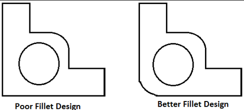
Sharp corners increase stress, which easily induced air entrapment, , air voids, and sink marks, thus weakening the structural rigidity of the plastic part. It must be eliminated using radii whenever is possible.
A bigger radius should be used if part design allows.
You can apply it on external and internal corners.
A bigger radius should be used if part design allows.
You can apply it on external and internal corners.
